|
As this is a fairly complex process I have created some images to help explain. These are not real photographs, but computer generated 3D models, there is a great advantage to this as it
allows me to use unnatural material colours and thus emphasise various aspects, and you will notice that I have chosen a quite stylised outboard motor type of propeller rather than a typical yacht propeller, as
again this emphasises various features that I wish to illustrate.
I would like you to imagine that the two vertical green rods are placed at 70% of the radius, so if this was a 14 inch diameter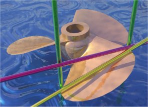 propeller the two green rods would be 4.9 inches out from the centre of the boss. Please note that this is not
necessarily the widest point on the blade. propeller the two green rods would be 4.9 inches out from the centre of the boss. Please note that this is not
necessarily the widest point on the blade.
As you can see, if you look vertically down on the propeller and measure the blade width at this point, you will in fact be measuring the Apparent Blade Width
along the line described by the red rod between the two green rods.
The True Blade Width is the distance along the yellow rod between the two green rods.
You will note that the red and yellow rods form a triangle with the vertical green rod. This is a right angle triangle with the 90 degree right angle formed between the red and green rods, and the
hypotenuse being the yellow rod.
While this will indeed give you the correct blade angle (at that point on the blade) please note that
this is not the pitch. The pitch _can_ be calculated from these angles and dimensions but it is far better to take the manufacturers data as stamped on the propeller. You should only calculate the
pitch from this data if you have no other source of data.
The Mean Width Ratio is the Average Blade Width in inches divided by Propeller Diameter
in inches, and so is a fraction usually of the order of such as 0.22
The Disc Area Ratio is calculated from the same viewpoint as the Apparent Blade Width, and is based upon the Projected Blade Area (imaging holding the propeller off the ground with the sun directly overhead, the area of shadow is Projected Blade Area) which as you can see from
the above illustration of true and apparent width, will be somewhat lower than the True or Developed Blade Area. The Disc Area Ratio is the ratio between the area of this Projected
Blade Area shadow and the area of a solid disk of equal diameter to the propeller.
|