
Having illustrated the commonest area of difficulty in Part One, we can progress to illustrate the other measurements. Again I have used exactly the same computer generated 3D models, but shown from
a different angle and with colouring in instead of coloured rods.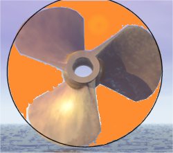
As you will see we are now looking at the propeller from more or less end on, when you come to do this in real life more or less is not good enough, but the slight deviation helps to illustrate the points somewhat.
The ratio of the Projected Blade Area to the area of the very badly drawn orange disc is the Disc Area Ratio. At a quick and dirty visual guess the prop on the left has a DAR of something like 55% or 55% of the disc area is blade.
For Mean Width Ratio we need to know the average blade width, the difficulty lies in working out the average width of a blade. In practice it is easier to work backwards from Disc Area Ratio and Propeller Diameter. You _can_ measure DAR by laying the prop flat on a clean piece of graph paper, place a suitable light source as high as possible above the boss to ensure parallel light rays and prevent the shadow from being bigger than the prop, and mark out carefully and then count up graph squares. It is a laborious process but it is reasonably accurate and low tech and will give results good enough to calculate with. Alternatively you can give the prop to a suitably equipped engineering shop who will measure the prop with CAD/CAM equipment and give you a very accurate answer in exchange for £1,000.