
OK, now we can go on to pitch measurement. In this first picture you will see that we are looking at the propeller from side on. If you can imagine that instead of water we were to turn the blade in a big block of some solid substance that was soft enough to cut, it is easy to see that the blade would move forward like a screw in wood. This is an important point, we must not include the slip that occurs in water, but we must imagine that the propeller is moving through a solid.
Again I have done some very poor quality drawing on the image, but then I am trying to illustrate a point 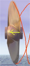 rather than win any prizes so all is not lost. As you can see, the yellow arrow indicates the
direction of progress along the line of the propeller shaft. The red lines are very badly drawn approximations of the paths of the tips of the blades as the propeller
rotates and thus moves forwards in this solid yet transparent material that we have invented to illustrate this point.
rather than win any prizes so all is not lost. As you can see, the yellow arrow indicates the
direction of progress along the line of the propeller shaft. The red lines are very badly drawn approximations of the paths of the tips of the blades as the propeller
rotates and thus moves forwards in this solid yet transparent material that we have invented to illustrate this point.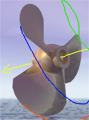
It is quite easy to visualise a single 360 degree rotation of the propeller describing a screw like path forwards through this material. It is also quite easy to visualise measuring the length of this track along the line of the yellow arrow to measure the pitch.
As you can see from this second equally badly illustrated picture on the right, we are looking at the propeller as it has just cut its way past our viewpoint. In this picture each blade has a different coloured trace to illustrate its track, and the gap between each trace, for example the red and blue, represents one third of the pitch (since this is a 3 blade prop). Clearly this is a very coarse propeller.
Hopefully these rather amateur sketches have illustrated the action of a moving propeller well enough so
that you can now imagine it without too much difficulty. I say hopefully because if you can then you are ready to do one of the hardest measurements which is pitch calculation. For this we need the original picture back again.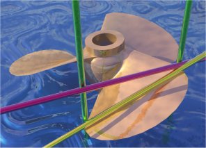
The point at which I should have drawn the traces in the previous pictures was not at the blade tips. I only drew them in there because it makes the screw in wood movement easy to illustrate so the user can grasp the principle. Now that you have grasped the principle we need to get back to the real world and a metal propeller in liquid water.
The place to measure is illustrated by the rods, at 70% of the radius out from the centre, we have this dimension from Part One as 4.9 inches. At this point we measure both true and apparent blade width and solve the right angle triangle to obtain the angle of the blade at this point. We will say for the sake of this example that this angle is exactly 30 degrees.
We now need to go back to the radius of 4.9 inches at which we measured true and apparent width, and obtain the circumference at this point or the distance travelled by this point in one 360 degree revolution of the propeller. This is obtained by converting the radius of 4.9 inches to a diameter of 9.8 inches and multiplying this by Pi (3.14) to give us 30.77 inches.
We can unravel this circumference into a straight line 30.77 inches long, and draw another line at an angle of 30 degrees as obtained previously. We can complete this drawing with a vertical line at 90 degrees to the first 30.77 inch line and we have another right angle triangle.
This new triangle has a known 30.77 inch line, with two known angles at each end, one 30 degrees and one 90 degrees. Since there are always 180 degrees in a triangle the remaining angle must be 180 - (90 + 30) = 60 degrees. We can then calculate that the hypotenuse is 35.5 inches, and the other vertical line is 17.7 inches (you may need to refresh your knowledge of Pythagoras)
The hypotenuse of 35.5 inches represents the distance travelled along the spiral track of the point on the blade 4.9 inches in radius out from the shaft in one 360 degree revolution of the propeller, and the figure of 17.7 inches represents the distance the propeller travels forwards in one 360 degree revolution, or the pitch.
We have now measured our unmarked and unidentified propeller sufficiently accurately to proceed with our calculations.